Adventures in hardware, part 7 - Stopwatch with a memory-mapped LCD controller
Hello stopwatch
I wanted to play a bit more with the 128x64 LCD display and the FPGA board, while also exploring the memory-mapping concept of the retro computers.
I thought I would like the LCD to display pixels/characters from memory, that would be mapped in the memory space of some device, so it would get written by something else (ideally a software running on a soft-CPU). While thinking of a reasonable demo project for the memory-mapping I thought of using the input switches as a primitive input device, but input handling felt like too much work for a proof-of-concept.
What did I build
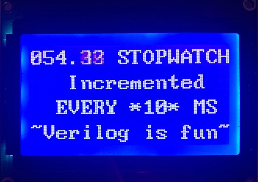
I ended up building an overly complicated weird stopwatch machine. It supports three digits for the seconds part and two digits for the hundredths of a second. The digits of the stopwatch get copied to a character buffer RAM, which gets copied to the external LCD controller.
How does it work
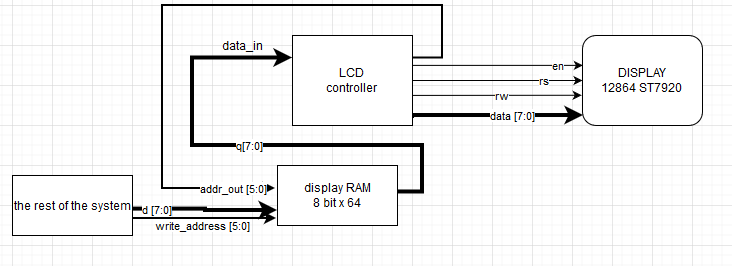
This schematic got drawn for the Reddit post where I got some leads.
Stopwatch
The stopwatch part is handled with a 5 digit binary-coded decimal (BCD) incrementer, that is toggled every 10 ms.
I initially designed the incrementer to explicitly work with 3 digits, but the code was a mess. I forgot about the principle of chaining/cascading, then rewrote it as a cascade of multiple one-digit BCD incrementers with chaining their carry signals.
The resulting single-digit BCD incrementer was much easier to work with and test:
module bcd_incrementer(
	input wire[3:0] bcd_in,
	input wire enable,
	output wire[3:0] bcd_out,
	output wire carry
);

//constants
localparam nine = 4'b1001;
localparam one  = 4'b0001;
localparam zero = 4'b0000;

assign bcd_out = enable == 1'b1 ? bcd_in == nine ? zero : bcd_in + one : bcd_in;
assign carry = enable == 1'b1 ? bcd_in == nine ? 1'b1 : 1'b0 : 1'b0;

endmodule
Display RAM
Nothing special here, a dual-port 64-byte RAM, where the main process can write data to and another process can read data from it.
Code: https://github.com/jborza/altera-12864-demo/blob/main/ram.v
Memory-mapping
Another piece of the puzzle is transferring the BCD digits to the display RAM. I ended up with this nasty state machine that either transfers a digit, a decimal dot or nothing to the target RAM address 0x0 - 0x7.
 always @(posedge clk)
 begin
	//update BCD
	we <= 1;
	ram_update_address <= ram_update_address + 1;
	write_address <= ram_update_address;
	case((ram_update_address))
		0: ram_in <= bcd[19:16] + ASCII_ZERO;
		1: ram_in <= bcd[15:12] + ASCII_ZERO;
		2: ram_in <= bcd[11:8] + ASCII_ZERO;
		3: ram_in <= ASCII_DOT;
		4: ram_in <= bcd[7:4] + ASCII_ZERO;
		5: ram_in <= bcd[3:0] + ASCII_ZERO;
		6: we <= 0;
		7: we <= 0;
	endcase
 end
LCD “controller”
The ST7920 display controller already is a driver/controller for the display, it already includes some display RAM, but I wanted to hide the implementation details from the rest of the system.
This unit is almost the same as one described in the previous post Adventures in hardware, part 6 - 128x64 display.
The main difference is that it’s connected to its display buffer RAM with a data_in and address_out wires, so it can read .
In this specific case of the ST7920 display with “16x4” character mode it sets up the display, then output 16 characters, move cursor to new line, output next 16 characters and repeat the lines 1-4 forever.
A funny bug along the way
I ran into a nice little bug - as I was refactoring my code I mistakenly changed a 11-bit 0xf constant into 0xffff (which is 16-bit) inside an if condition:
reg  [10:0] counter; //range 0-2047

if(counter==16'hffff) begin	//0xffff is 65535
    clk_divided <= ~clk_divided;
end
Of course, the synthesizer noticed my mistake, and realized the counter is never going to reach the constant, so that condition won’t get satisfied, so it decided I’m never going to do anything with the clk_divided output and got rid of the entire logic in my LCD controller.
The finished product
Testing and simulating the BCD incrementer with ModelSim
ModelSim woes
The workflow of getting a testbench working was a bit stranger than with Xilinx ISE+ISim toolkit. The tooling seemed to guide me into creating the test bench in the simulation/modelsim directory, once when I generated a test bench template for my top module with
Processing->Start->Start Test Bench Template Writer, the second time when launching the simulator from within Quartus.
The way it worked for me was to place the test bench (.vt files) in the same directory as the .v design files. After ModelSim was launched I’d Change Directory into my main project directory.
Then after each change in the design or test giles I had to:
- recompile the library files with Compile->Compile… (or right and Recompile)
- restart the simulation with with Simulation->Restart…
- run the simulation with Simulation->Run->Run -All
This mostly means that I should read more about ModelSim, but I was more interested in moving on with the project, rather than spending an afternoon with a new simulator 😁.
Simulation testbench
I found Verilog testbenches to be more compact than VHDL testbenches. It may be because I like the syntax of Verilog tasks that helped me make the code more readable:
task debug_print;
	input [3:0] expected;
	input carry_expected;

	begin
		#10; $display("in = %b [%d], out = %b, carry = %b, expected = %b", bcd_in, bcd_in, bcd_out, carry, expected);
		if(expected != bcd_out || carry != carry_expected)
		begin
			$display("^^^ value vs expected is different!");
		end
	end
endtask

...

#1; bcd_in = 4'b1000; //8
 debug_print(4'b1001, 1'b0); //9

#1; bcd_in = 4'b1001; //9
 debug_print(4'b0000, 1'b1); //10
Side-notes
Verilog coding style
I’m still not sure whether I like more declaring the inputs and outputs within the module declaration (as per Verilog-2001):
module bcd_incrementer(
	input wire[3:0] bcd_in,
	input wire enable,
	output wire[3:0] bcd_out,
	output wire carry
);
Or immediately after the declaration along other wires and registers, which also means declaring them twice (Verilog-1995):
module bcd_incrementer_5digit(
	bcd_in,
	bcd_out,
	enable
);

//inputs and outputs
input wire [19:0] bcd_in;
output wire [19:0] bcd_out;
input wire enable;
I’ll try to read more books, articles and source code to see what makes more sense.
Making the gif
I shot the screen with my phone camera again, then converted it into a gif with This time it made more sense to skip palette generation:
ffmpeg -i input.mp4 -vf "transpose=2, scale=320:-1:flags=lanczos" -loop 1 output2.gif
Is this a reasonable design?
Probably not. As AndresNavarro correctly pointed out in his Reddit comment, the ST7920 is already a driver/controller for lcds, and the idea is it makes it easier to control an lcd from a sequential program (typically in a microcontroller) and it feels hacky.
This entire thing would probably have taken 20 lines of code with Arduino libraries.
I agree, but it was still fun. It probably makes more sense in the context of pixels and framebuffer, rather than characters. With that one could implement a character generator ROM, connect it to a VGA interface and end up with a text display.
The code repository
Hosted with ❤️ on GitHub: https://github.com/jborza/altera-12864-demo