In the previous articles I’ve mainly interfaced with LCD displays. I thought it would be nice a produce a VGA output from my FPGA board. I’ve already had a working framebuffer-based display controller that can be written to through a serial port, so this was a matter of developing a bitmapped VGA controller.
Target resolution - 320x240 over 640x480
Why 320x240? Because my development board only 276.5 kbits of memory. To fit a 1-bit 640x480 framebuffer I would need 307.2 kbits.
However, 320x240 is not a standard VGA resolution, but can be easily achieved using a 640x480 resolution and doubling each pixel.
VGA controller
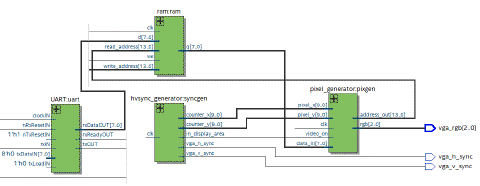
There are two main modules to the VGA output - the timing and sychronization signal generator and a pixel generator, connected to the framebuffer.
hvsync_generator generates timing and synchronization signals
hsync and vsync are sent to the monitor, decoded from internal counters
pixel_x and pixel_y specify the location of the current pixel
video_on genrated to enable or disable the display (e.g. in display area)
Horizontal and vertical synchronization
The timings are much better described elsewhere, for example here
, here
and on stackexchange
.
Very briefly, in addition to the active 640x480 drawing area, there are also borders / porches that relate to the analog (CRT) monitor internals - electron beams, sawtooth generators and such that needed to be driven by these and the hsync and vsync signals.
This makes up to an effective resolution of 800x525, adding the display area, all porches and the sync rows/columns.
The pixel clock
As the entire area contains 800 “pixels”/line * 525 lines/frame. To achieve 60 frames per second as per the specification, we arrive at
I was lazy again and divided the internal 50 MHz clock by two to get 25 MHz clock, which is off by 0.7%. Technically this is deviating from the standard, as it allows 0.5% difference, but all of my monitors handled the signal fine.
Framebuffer / Memory layout
I initially started with a simplistic 320*240=76800-bit memory, indexed from 0 to 76799
localparam RESOLUTION_X =320;
localparam RESOLUTION_Y =240;
reg mem [0:RESOLUTION_X*RESOLUTION_Y-1];
This lead to a simplistic pixel generator that just reduced the 640x480 resolution to 320x240 by dividing each coordinate by two:
Although this makes it very practical to read a particular display value in a single clock, but impractical to interact with in terms of interfaces - the current serial interface that sends bytes over UART or a future 8-bit soft-CPU, dealing with bytes is nicer than dealing with bits.
To move from this convenient 1-bit interface to 8-bit interface I had to redefine the memory to:
reg [7:0] mem[0:(320*240/8-1)];
To cover 320x240 bits we split the framebuffer memory into 9600 words of 8-bits. That also means that one word will cover 8 contiguous pixels.
Divide and conquer
In the spirit of dividing responsibilities into modules I implemented a m640_to_320 module that produces the byte and bit part of the framebuffer. We can extract the bit part easily as it’s just the remainder of (x / 2) and 8, then inverted as we store pixel bits in “little endian” ordering.
The pixel generator then obtains the address_byte and address_bit from this module.
As using the block RAM introduces a single clock delay we need to store the value of address_bit into a register to be available on the next clock cycle when the memory value actually arrives.
so on every clock cycle the pixel generator module:
fetches the correct byte from memory
draws the correct color from currently retrieved byte with the previous value of address_bit
Note: I spent some time chasing down a bug where some 8-th pixel had incorrect colors as I didn’t immediately realize that I needed the 1-clock delay.
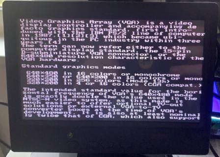
After fixing that, the display worked well - here’s a sample of a how a text mode would look like: (the bitmap that was sent to the FPGA was generated on my computer with 8x8 font).
Sending some text over the serial interface
Serial interface
It’s unchanged from my previous LCD serial display post
- just the framebuffer is now larger.
Sending 1-bit PNG
I have a small Python script
that reads a 320x240@1-bit PNG picture, converts the pixel values into bits that one can redirect into the serial port from command line.
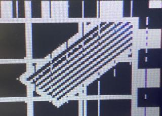
Screen-to-serial capture
To have a bit more fun with the display, I wrote a little utility in C# that captures the screen, performs dithering and sends the bits over the serial port.
This is all possible using the standard APIs - we can capture the screen with the Graphics.FromScreen, then resize the picture into 320x240, do the dithering by fiddling with the Bitmap’s pixels, then write to System.IO.Ports.SerialPort.
Although modern computers are fast, there’s a limit to what we can achieve with naive codea approach. As this was single-core heavy, reducing the desktop resolution to 800x600 helped increase the performance of the bitmap scaling part. Using 3 MBaud bitrate allowed me to transmit around 15 frames per second to the FPGA board.
I think this qualifies as a crude external video card :)
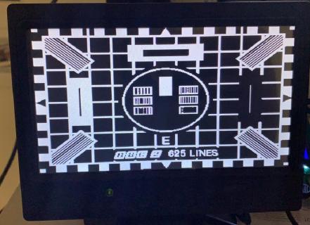
A test pattern
I hooked the board to a smallish 7" LCD screen with HDMI, composite video an VGA.