Adventures in hardware, part 3 - display and a calculator
Let’s do a calculator
Let’s make a very simplistic 3-bit calculator that will:
- add or subtract number A and B
- number A is entered by DIP switches 1,2,3
- number B is entered by DIP switches 4,5,6
- operation (+/-) is defined by DIP switch 8
| number | DIP | LED |
|---|---|---|
| A | 1,2,3 | 1 |
| B | 4,5,6 | 2 |
| A+B / A-B | 8 | 3 |
To do that, we would need two instances of a “number display” that would display each of our 3-bit numbers (A, B) on their respective displays. Then we would need some logic performs arithmetics on the numbers resulting in a 4-bit number (result) that would be displayed on the third display in hexadecimal format.
This is how it should look in the end:
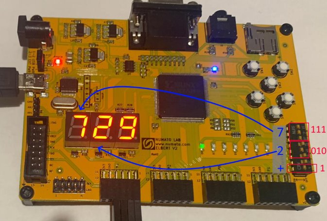
Making a small display
The Seven-segment display configuration on Elbert v2 is wired as follows:
        1
      ____
   6 |    | 2
     |_7__|
   5 |    | 3
     |____| .0
       4
It actually contains eight segments - seven for the number and eigth for the decimal point.
To display a 3-bit input Number, I’ve used the VHDL with ... select statement and just listed the combinations of the active segments. Note that the display uses an active-low (common anode) configuration, so the segments that are sent digital 0 are turned on (contrary to what I expected).
    Port ( SevenSegment : out  STD_LOGIC_VECTOR (7 downto 0);
           Number : in  STD_LOGIC_VECTOR (2 downto 0));
...
	with Number select
		SevenSegment(7 downto 1) <=
			"0000001" when "000", --0
			"1001111" when "001", --1
			"0010010" when "010", --2
			"0000110" when "011", --3
			"1001100" when "100", --4
			"0100100" when "101", --5
			"0100000" when "110", --6
			"0001111" when others; --7
		SevenSegment(0) <= '1'; --decimal point
The
otherskeyword is similar to adefaultcase in switch in C or Java.
We can make a 4-bit display module similarly by extending the patterns to go from 8 to F.
Driving the display
Elbert v2 has an on-board multiplexed display. The data bus for the entire 3-digit display is connected by 8 wires (one for each segment), we need to toggle between the digits using the Enable signal.
We can handle this by introducing a “driver” component, that will receive
- clock signal
- three 8-bit seven-segment inputs A,B,C (for digits 1,2,3) and output
- 8-bit seven segment output
- 3 enable bits with a specific digit being on at a time
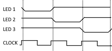
And we expect it to display the number 1 on a first clock cycle, number 2 on a second clock cycle, number 3 on the third cycle, and repeat.
Doing it on every cycle actually turned out to be wrong, the display can’t refresh as fast as in the megahertz range, so we need somewhat longer cycles. We can achieve that by using a “clock enable” - simulating a slower clock as this StackOverflow post.
We can use a 16-bit counter, that will toggle a signal everytime it resets, yielding an effective frequency of 12,000,000 / 65,536 ~= 183 Hz. That gives us around 60 Hz
--process to generate slower refresh period than the main clock
process(Clk12Mhz)
begin
	if rising_edge(Clk12Mhz) then
		clk_refresh_counter <= clk_refresh_counter + 1;
		if(clk_refresh_counter = 0) then
			clk_refresh <= '1';
		else
			clk_refresh <= '0';
		end if;
	end if;
end process;
Then we can use a case statement to explicitly map the current state to the output bits and the next state:
process(clk_refresh)
begin
	if rising_edge(clk_refresh) then
		case digit_counter is
			when "00" =>
				SevenSegment <= A;
				Enable <= "011";
				digit_counter <= "01";
			when "01" =>
				SevenSegment <= B;
				Enable <= "101";
				digit_counter <= "10";
			when others =>
				SevenSegment <= C;
				Enable <= "110";
				digit_counter <= "00";
		end case;
	end if;
end process;
Simulating the driver
We can create a VHDL test bench to test the behavior of the driver.
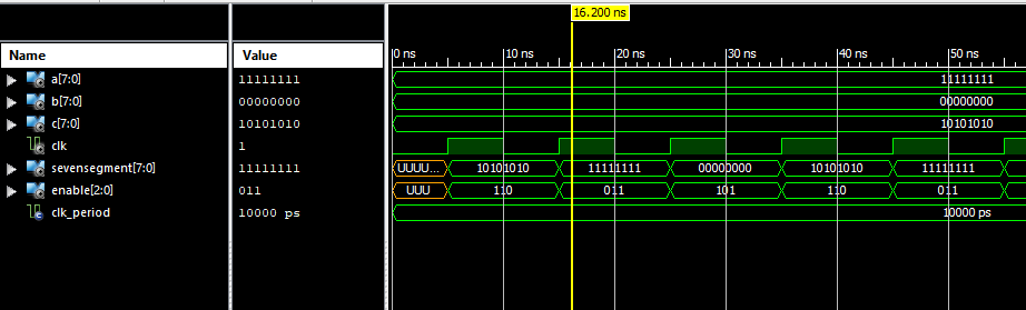
The simulator is set up as:
signal A : std_logic_vector(7 downto 0) := "11111111";
signal B : std_logic_vector(7 downto 0) := "00000000";
signal C : std_logic_vector(7 downto 0) := "10101010";
and we’d expect this to happen on the clock cycles:
| output | tick | tick | tick | tick | tick | tick |
|---|---|---|---|---|---|---|
| SSeg | 11111111 | 00000000 | 10101010 | 11111111 | 00000000 | 10101010 |
| Enable | 011 | 101 | 110 | 011 | 101 | 110 |
And we can see the same happening in the ISim simulator:
Adding (and subtracting) the numbers
Now we need to add (or subtract) the two numbers based on the DIP switch 7. When it’s on, result=a+b, else result=a-b.
Because VHDL is strongly typed, we will also need to convert std_logic_vector buses to actual unsigned numbers for the arithmetic operators, and convert result back to std_logic_vector for display.
```vhdl –signal of the arithmetic operation do_add <= not DPSwitch(7);
--add or subtract the numbers
process(Clk)
begin
	if rising_edge(Clk) then
		number_a <= unsigned(not DPSwitch(2 downto 0));
		number_b <= unsigned(not DPSwitch(5 downto 3));
		if do_add = '1' then
			result <= number_a + number_b;
		else
			result <= number_a - number_b;
		end if;
	end if;
end process;
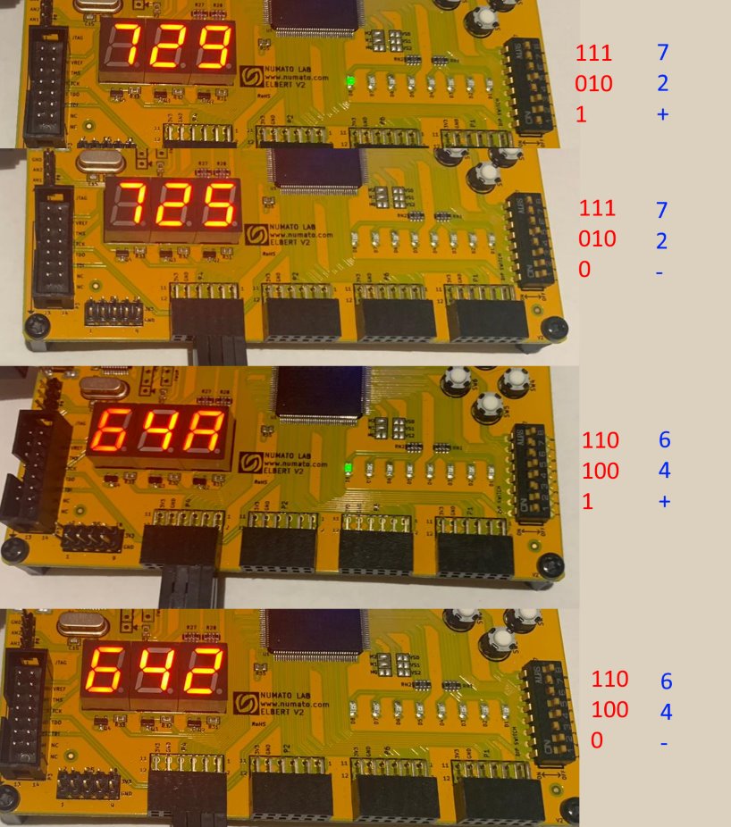
How does it look?
I’ve taken a couple of pictures with the DIP switches in various positions:
Source
The code is available at GitHub repository jborza/elbert_sevenseg_calc.